Assembly Steps
Before you start, ensure you have all necessary parts and tools.
Video Tutorial:
This video shows the assembly process of the HackHeld Vega II Kit. It follows the same steps as described below. Use it as a reference if you are unsure about any step. The chapter marks in the video allow you to jump to a specific step.
1. D1 Mini
-
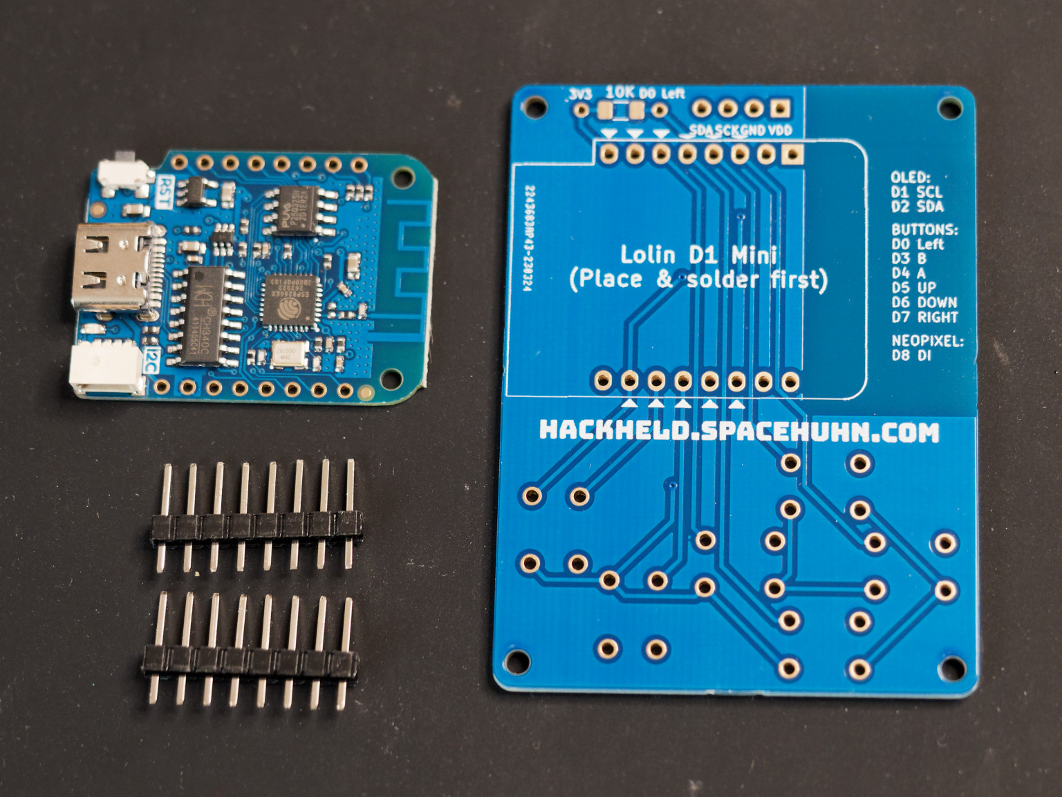
Take the HackHeld Vega PCB, the D1 Mini, and the header pins.
-
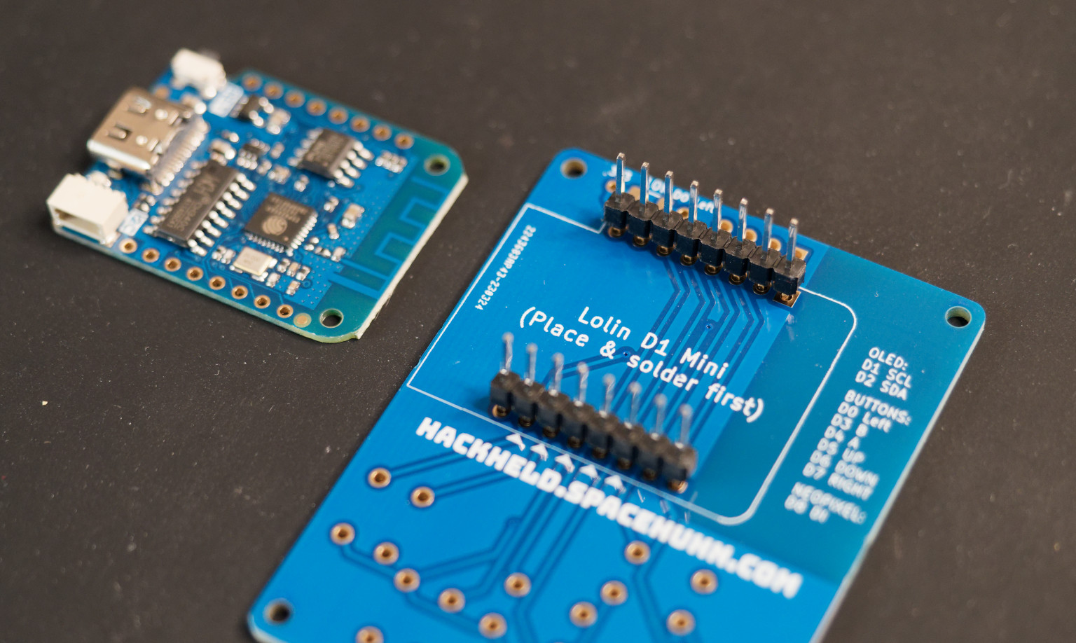
Place the header pins onto the PCB. The shorter end goes into the PCB.
-
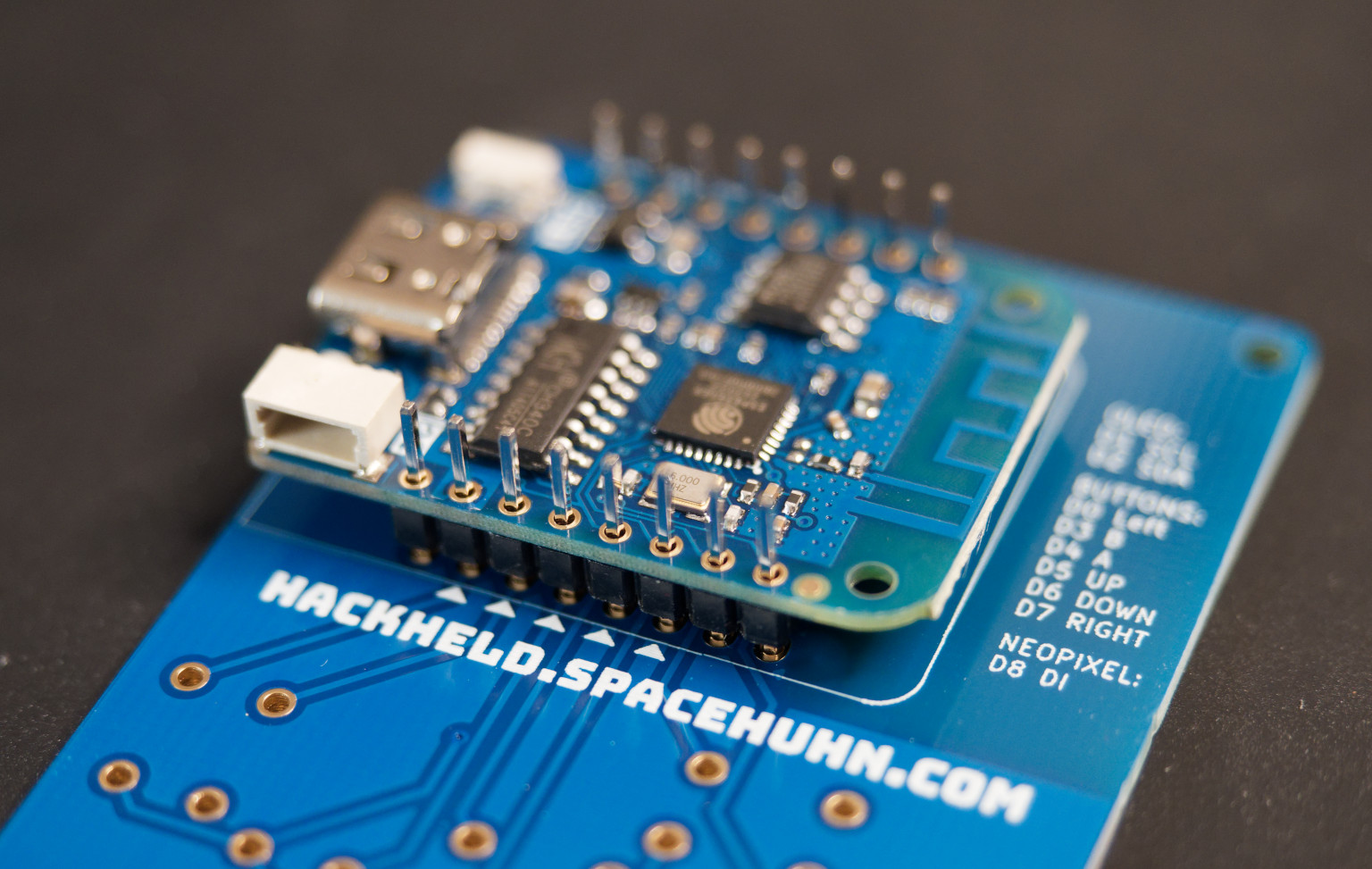
Place the D1 Mini onto the header pins. Make sure it is sitting straight on the PCB.
-
Solder one header pin to the D1 Mini. This will fix the D1 Mini in place.
-
Make sure the D1 Mini is sitting straight on the PCB. Then solder the remaining header pins.
-
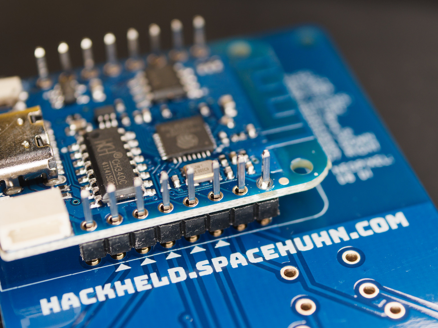
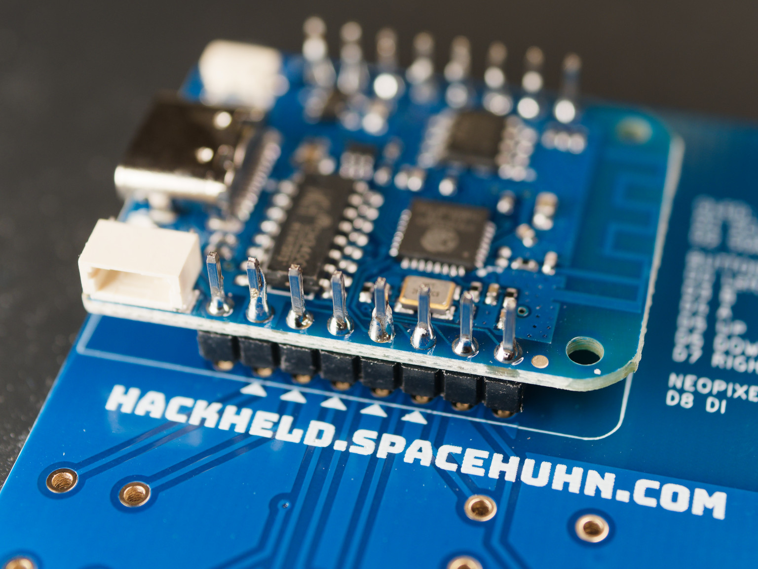
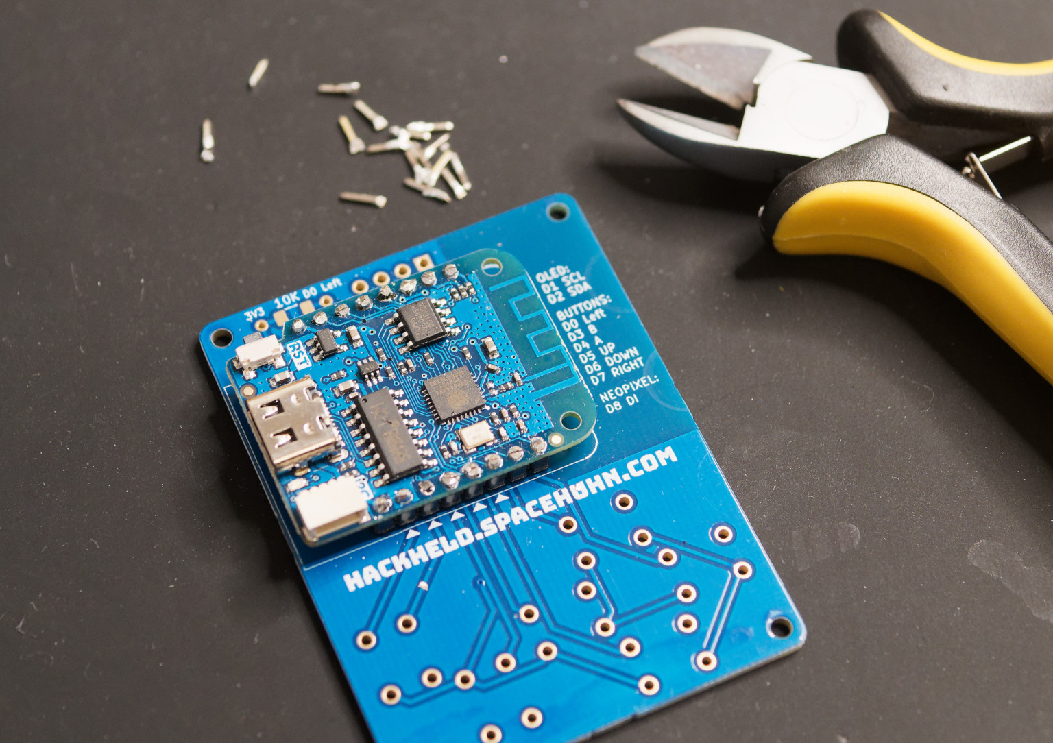
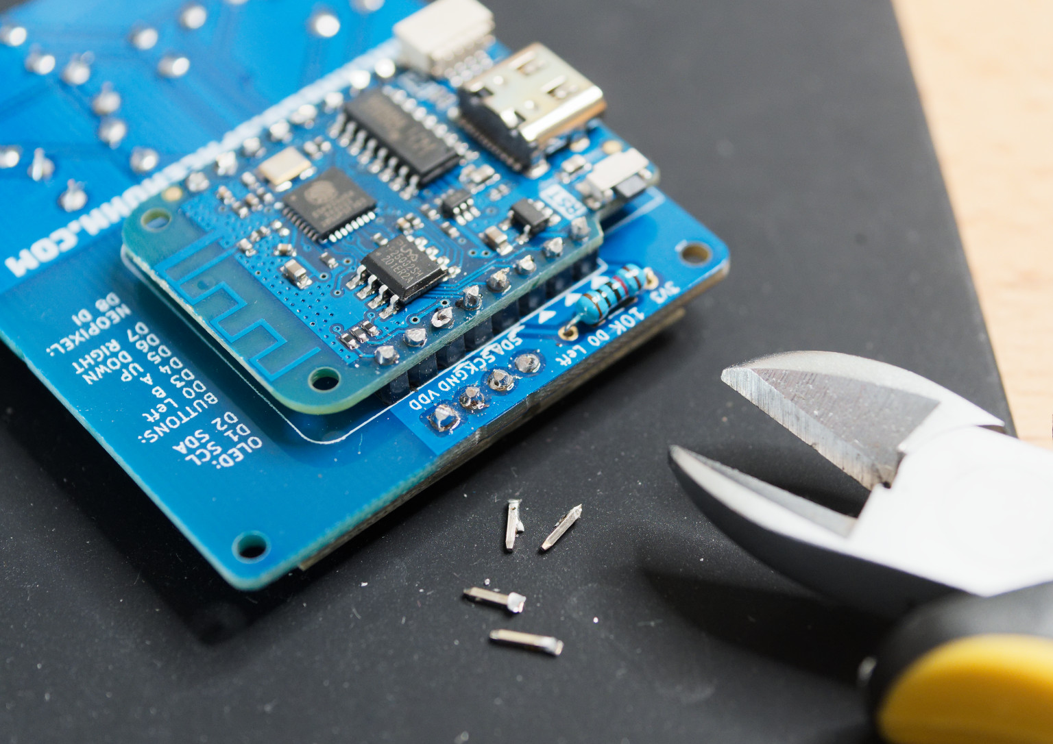
Cut header pins of the D1 Mini. ⚠️ Be careful to hold them in place while cutting. They tend to fly away towards your eyes. ⚠️
-
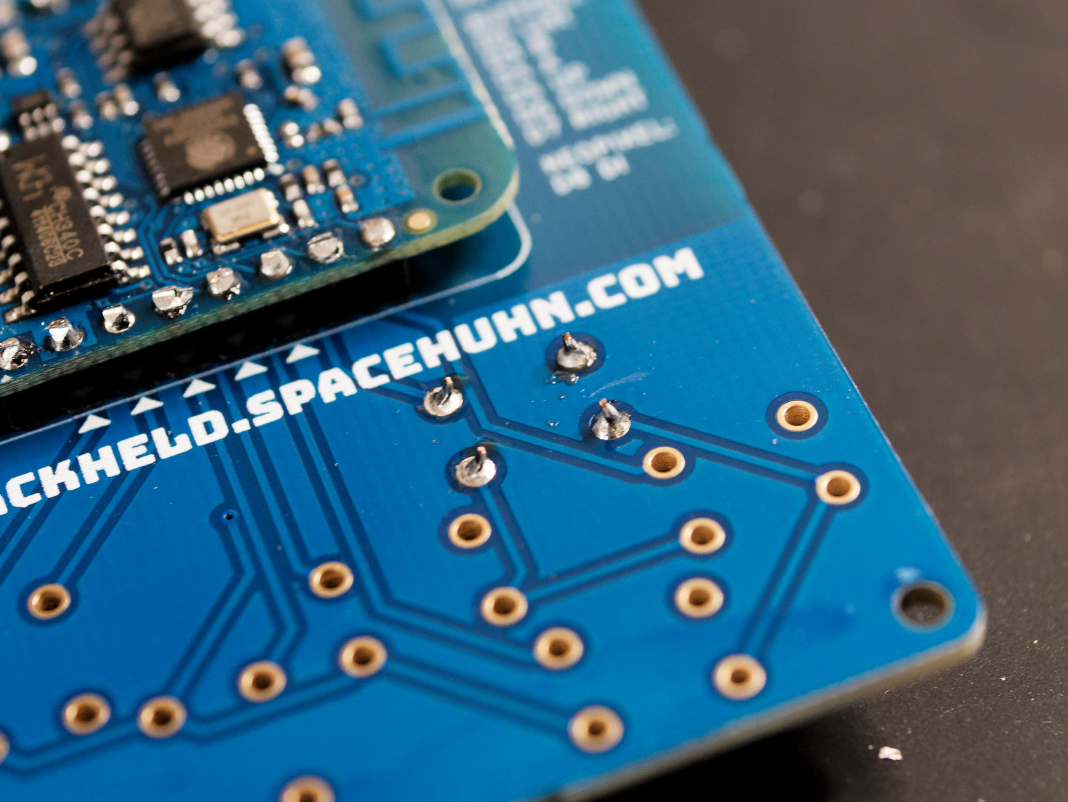
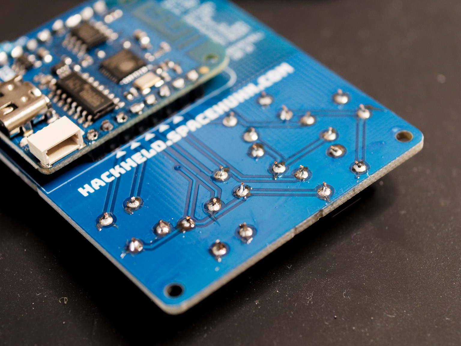
Turn around the PCB, but keep the D1 Mini in place. Make sure the D1 Mini is sitting straight on the PCB before soldering.
-
Solder the D1 Mini to the PCB. (You only have to solder pins with a text label, but you can also solder the others to make it more stable.)
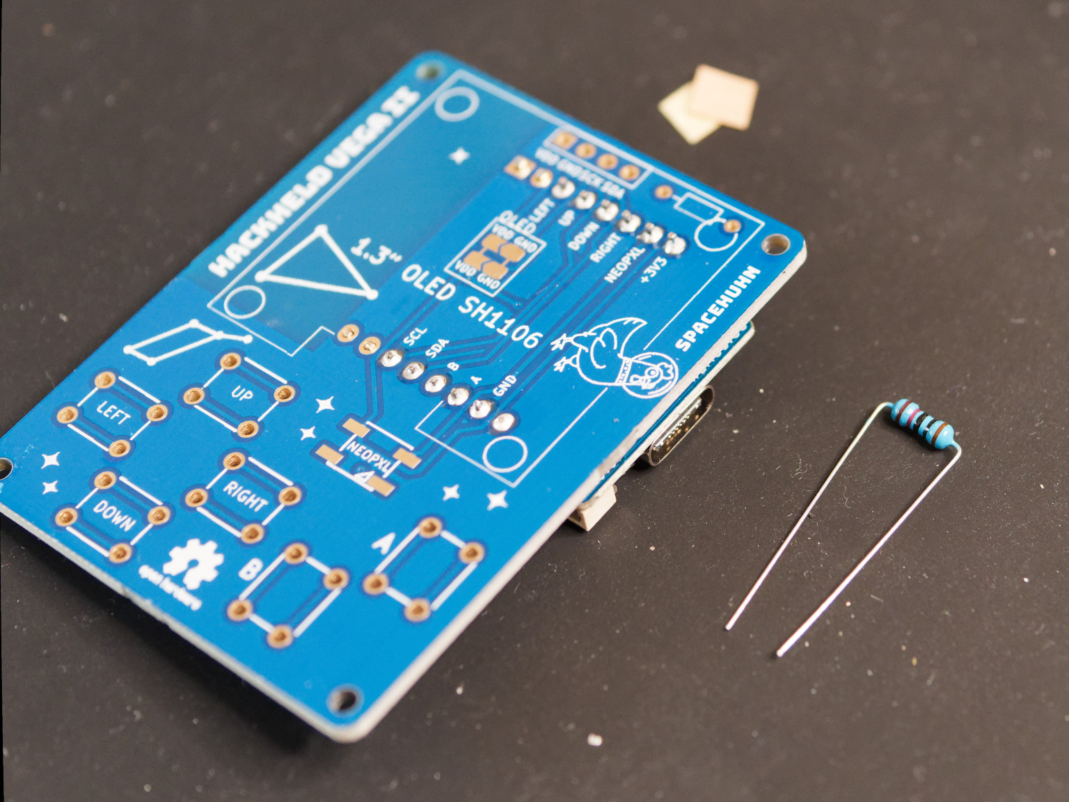
3. Resistor
-
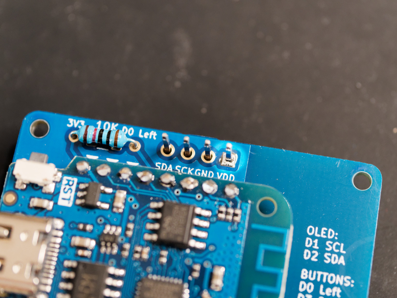
Take the 10k resistor and remove the isolation from the ends.
-
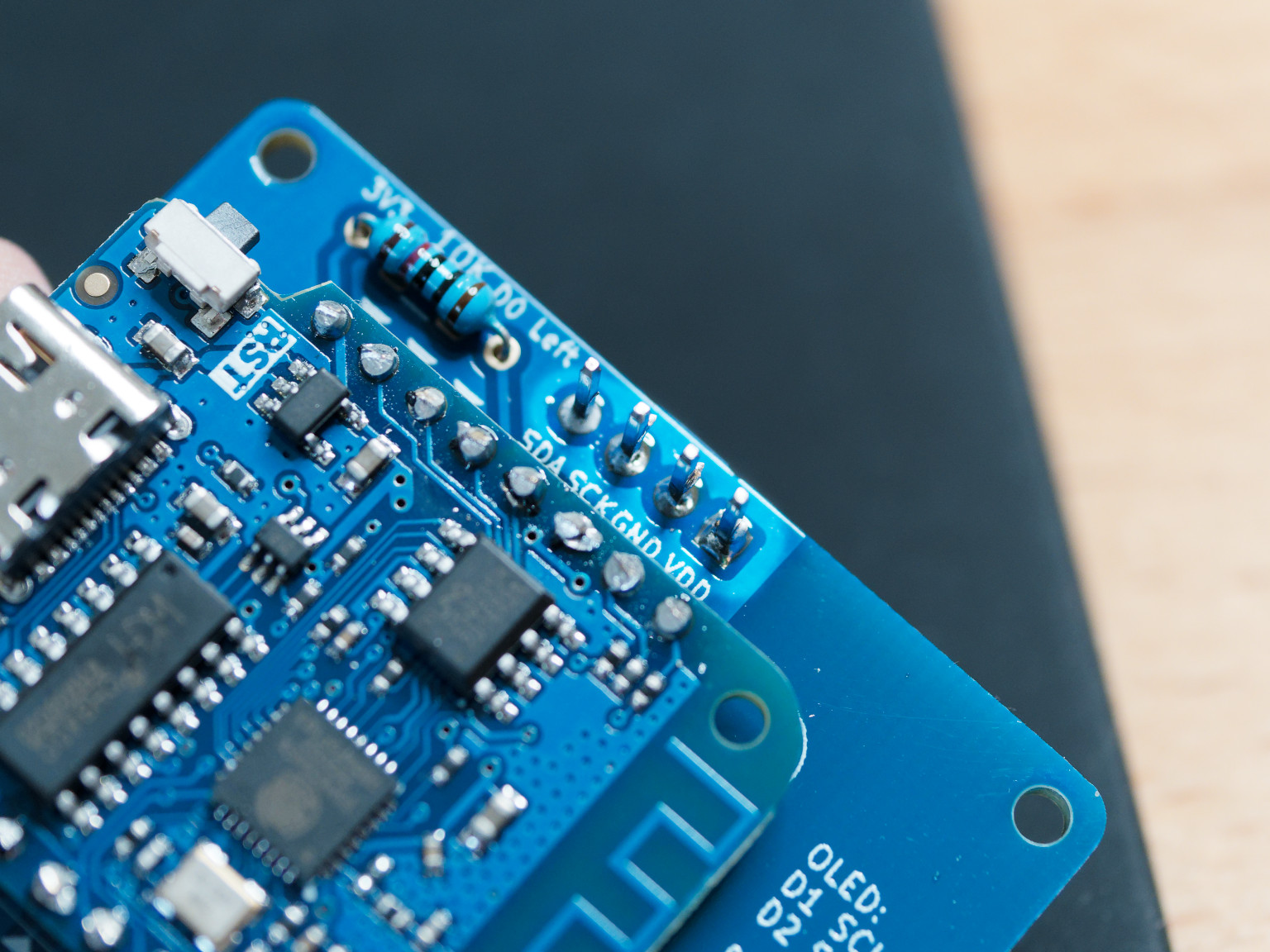
Place the resistor on the backside of the PCB.
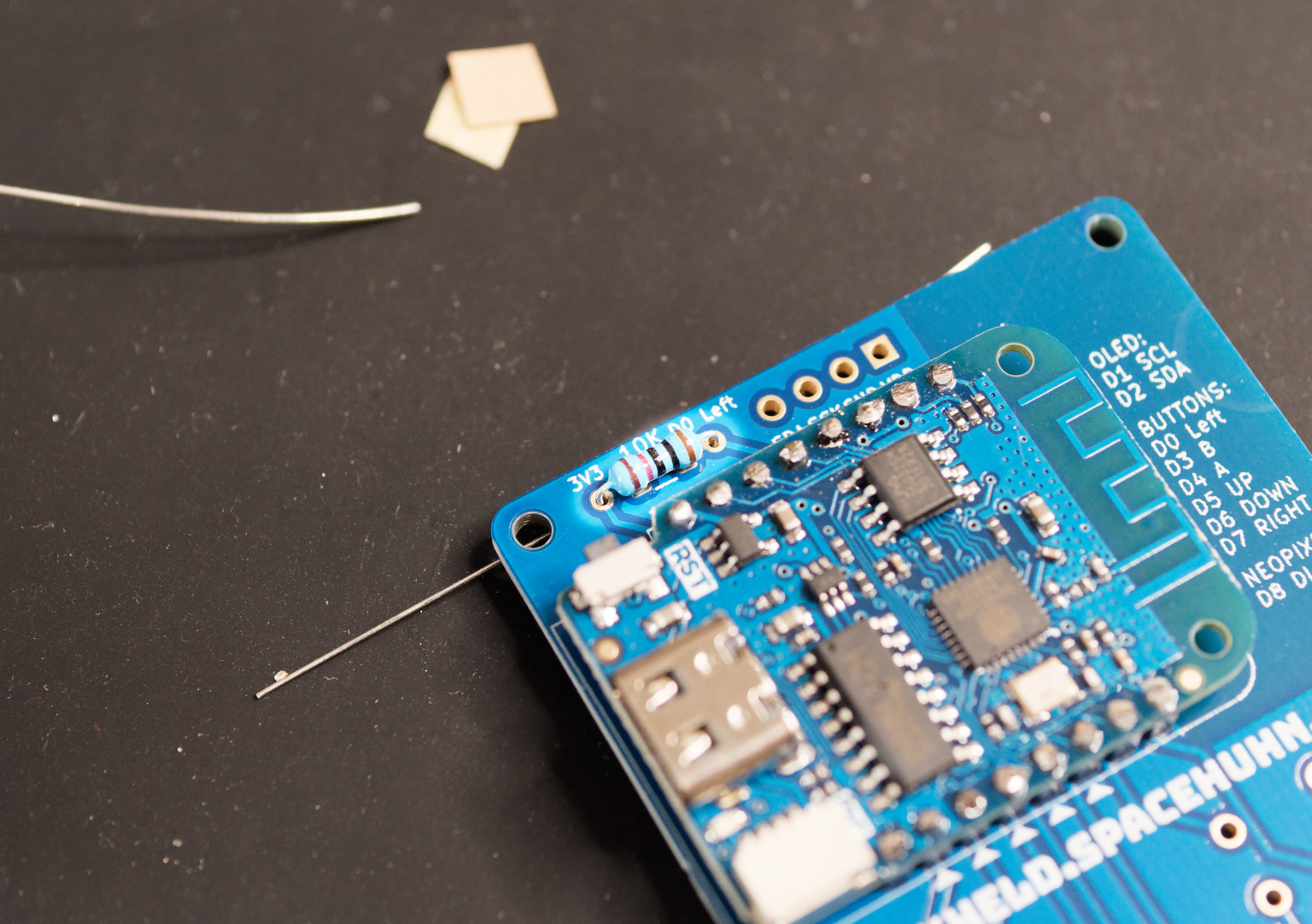
-
Solder the resistor to the PCB.
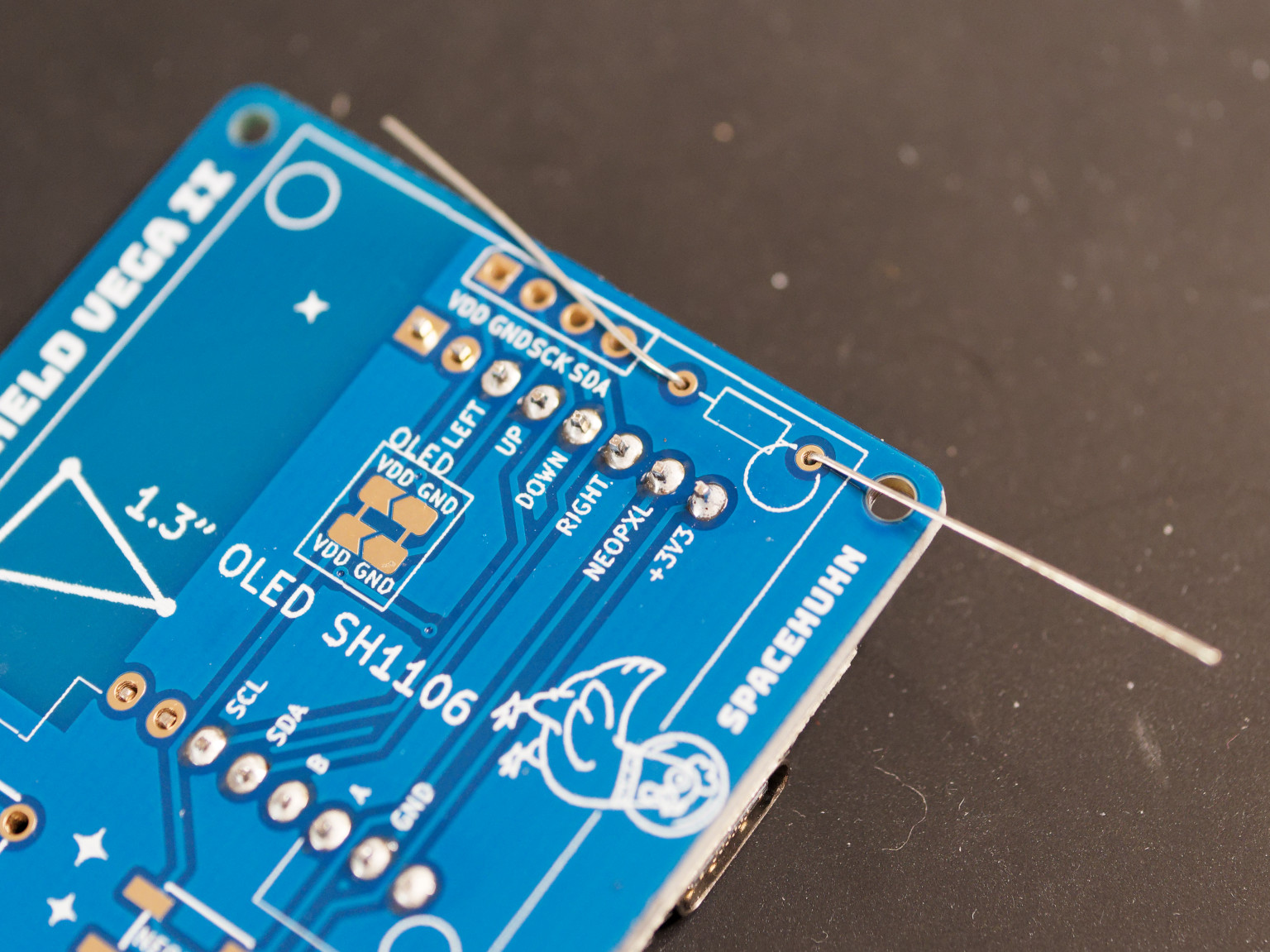
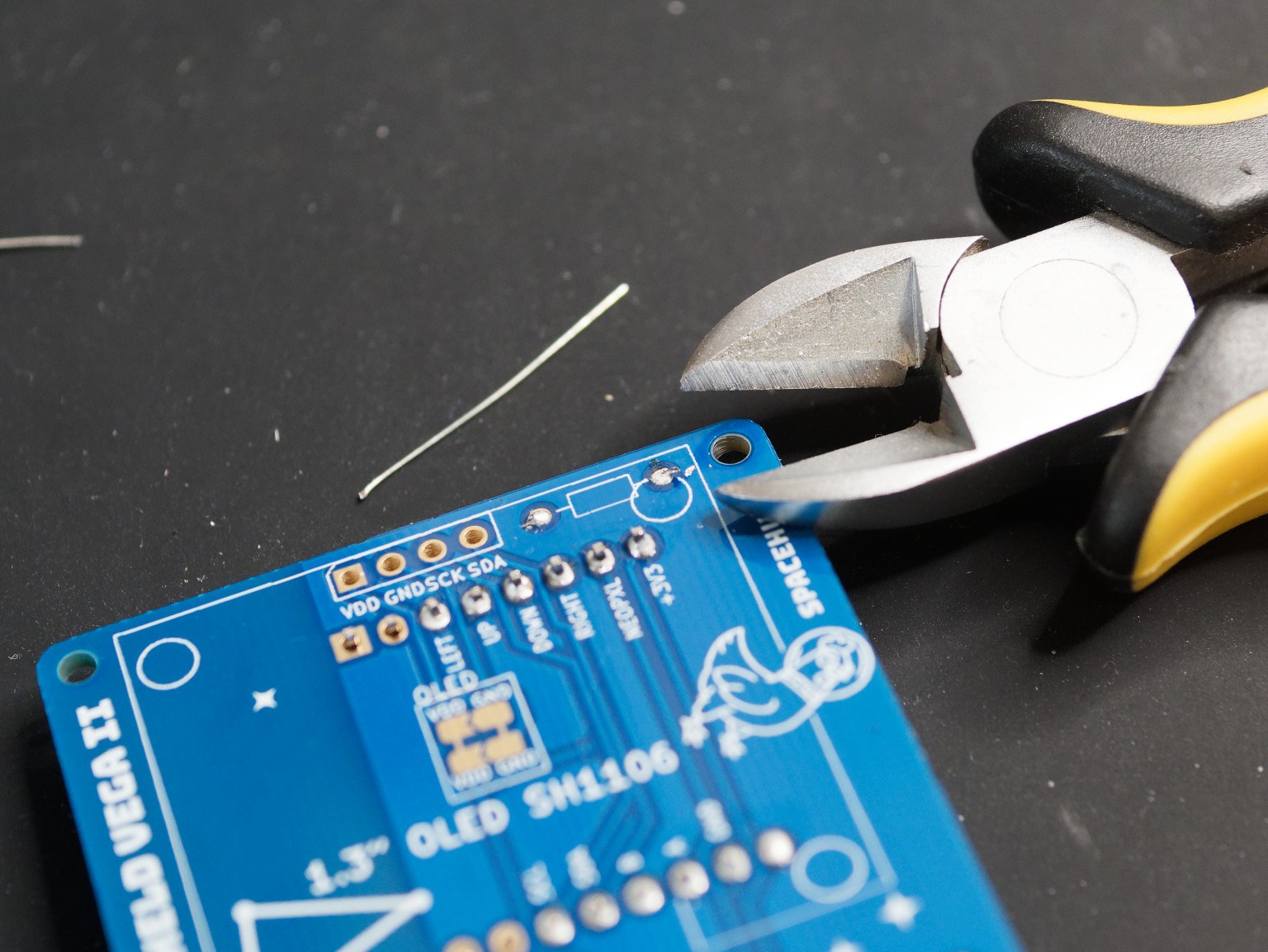
-
Cut the ends of the resistor.
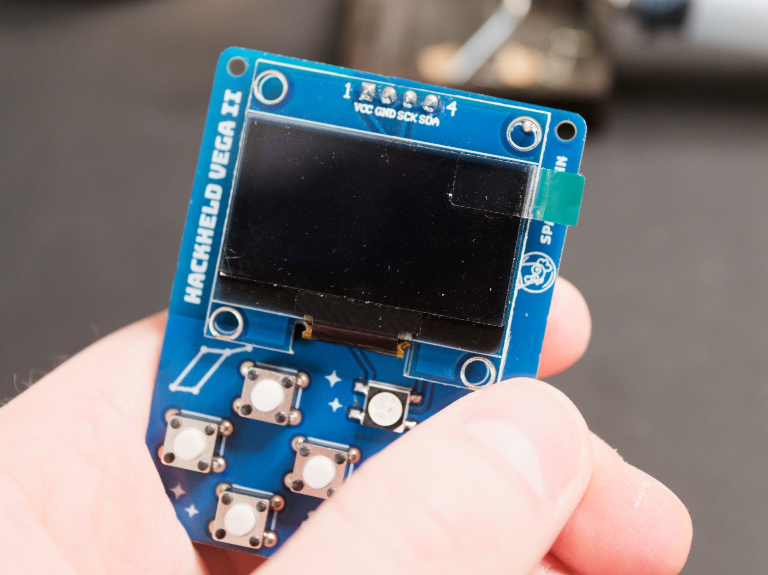
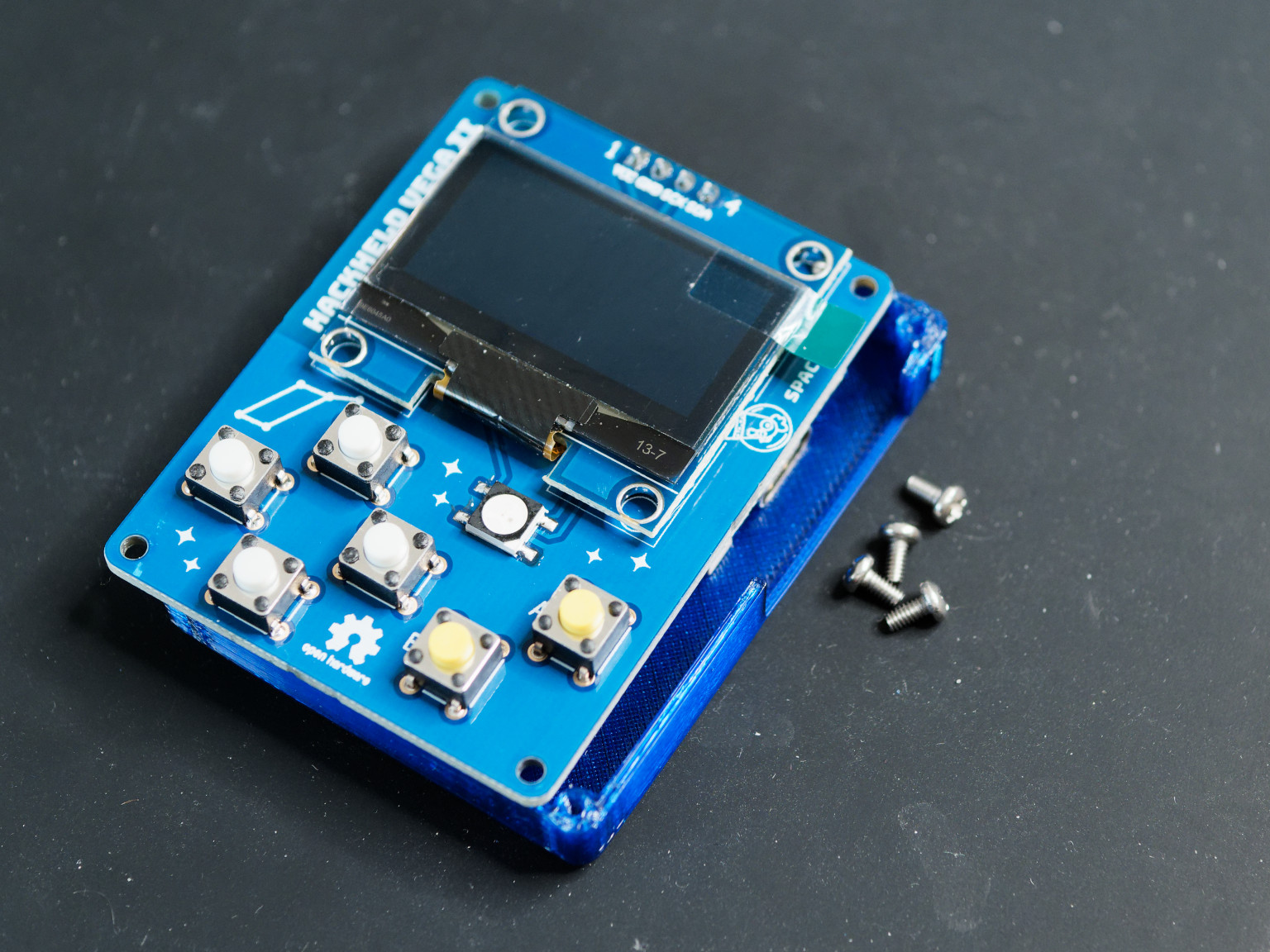
4. Buttons
-
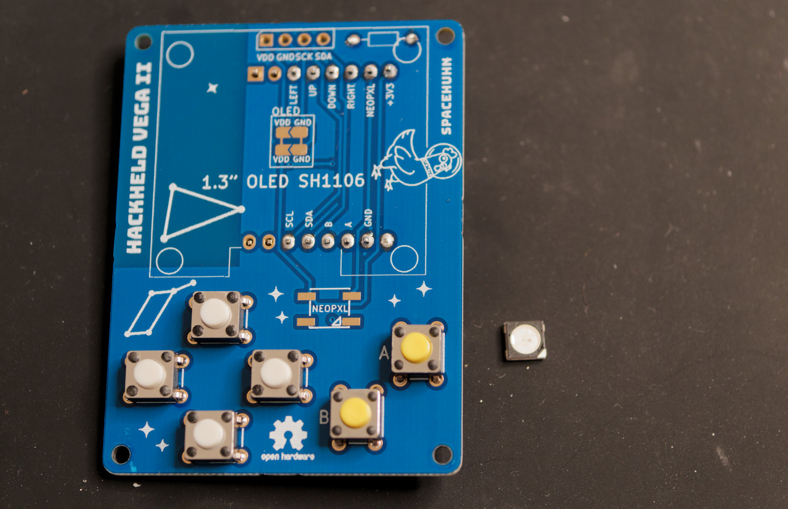
Take the buttons and the PCB. The kit includes 4 white buttons and 2 yellow ones. The yellow ones are for the
AandBbuttons. But the colours make no difference, so you can place them anywhere.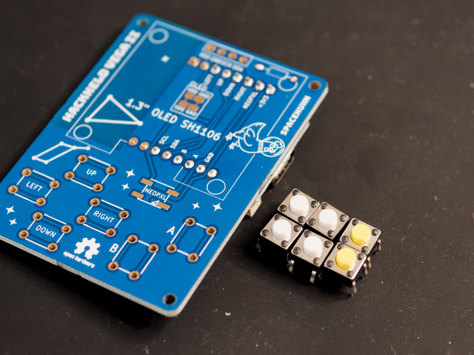
-
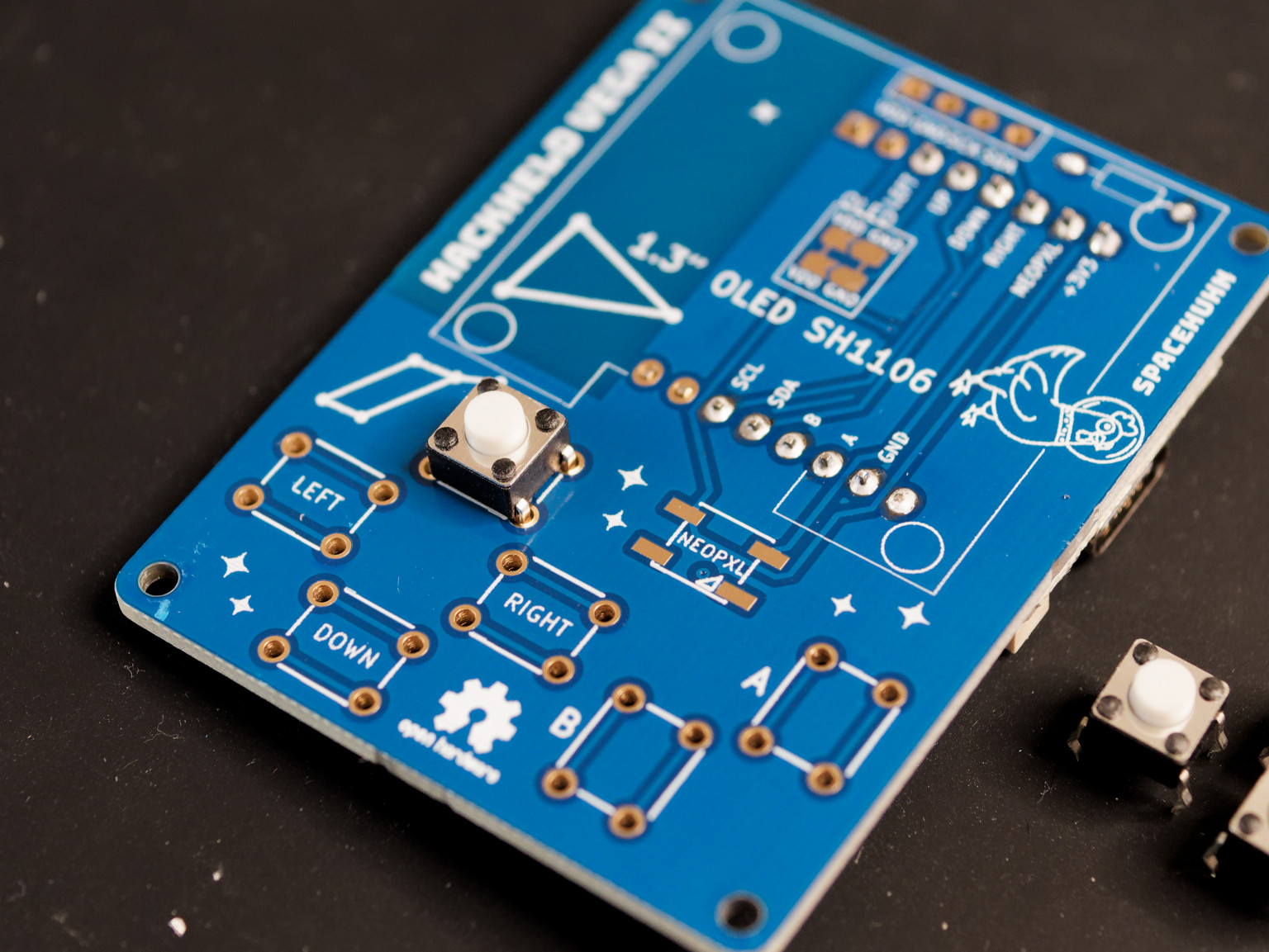
Take one button and place it into the PCB. Make sure the button is sitting straight on the PCB.
-
Solder one leg of the button to the PCB. This will fix the button in place.
-
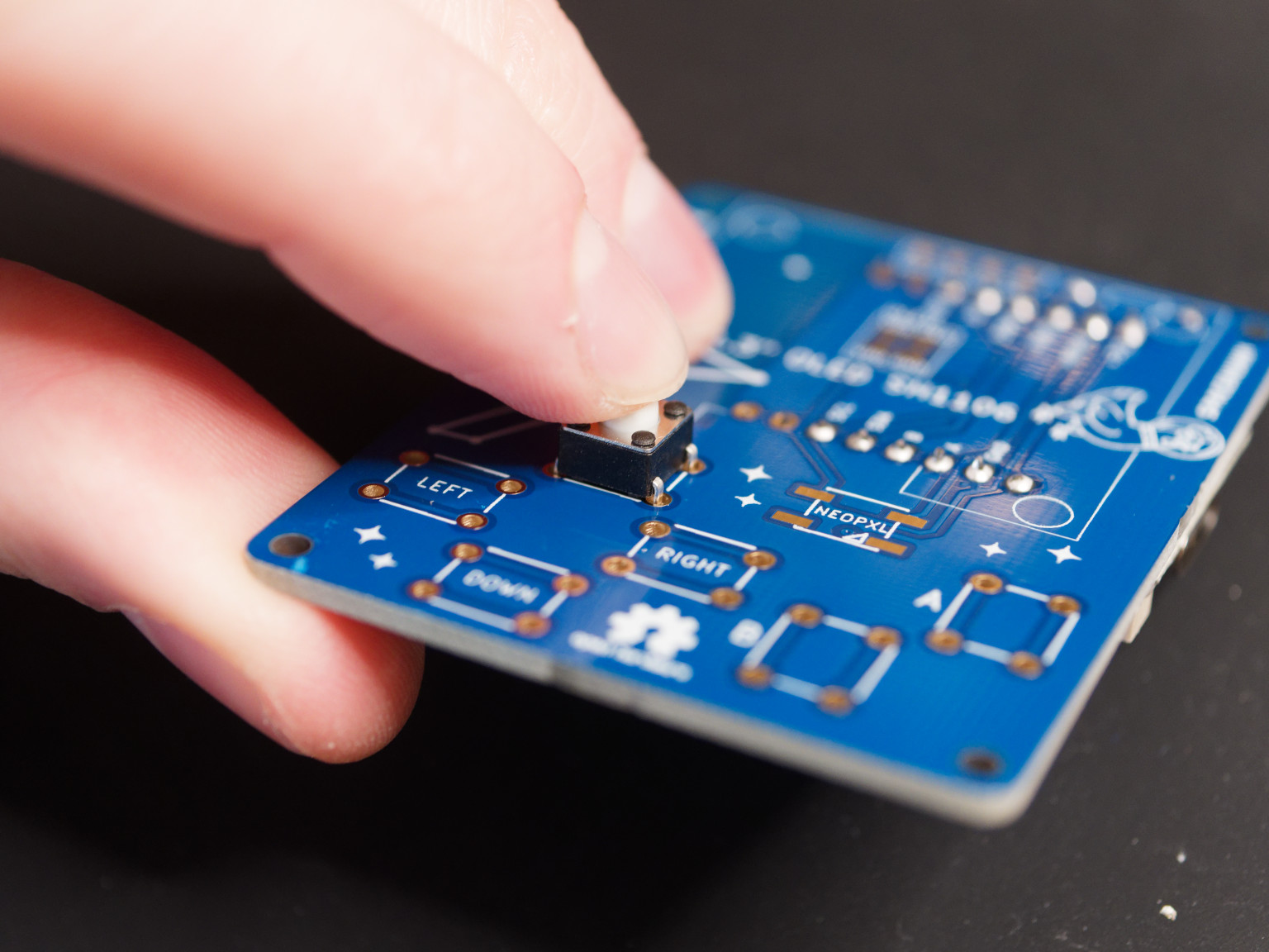
Press the button to ensure it sits straight on the PCB.
-
Solder the remaining legs of the button to the PCB.
-
🔁 Repeat steps 2-5 for the remaining buttons.
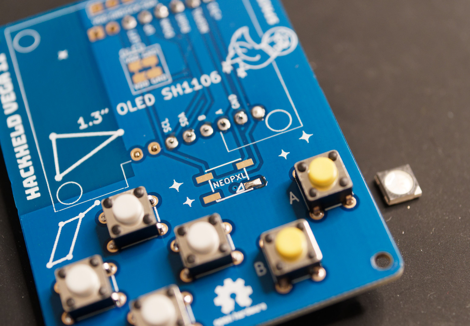
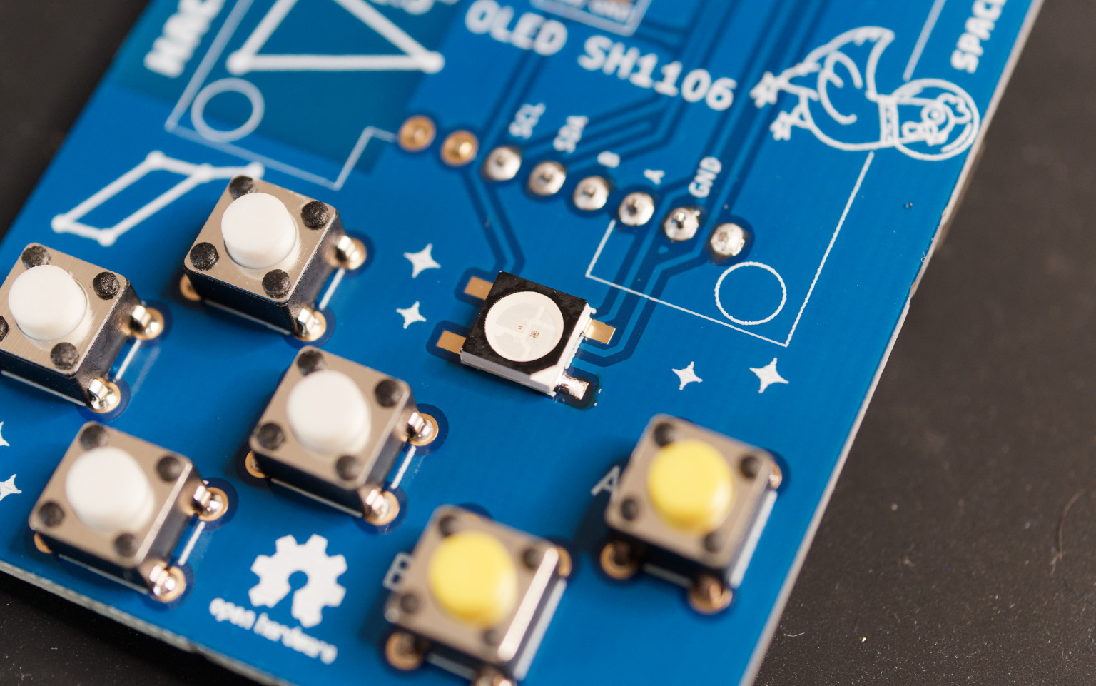
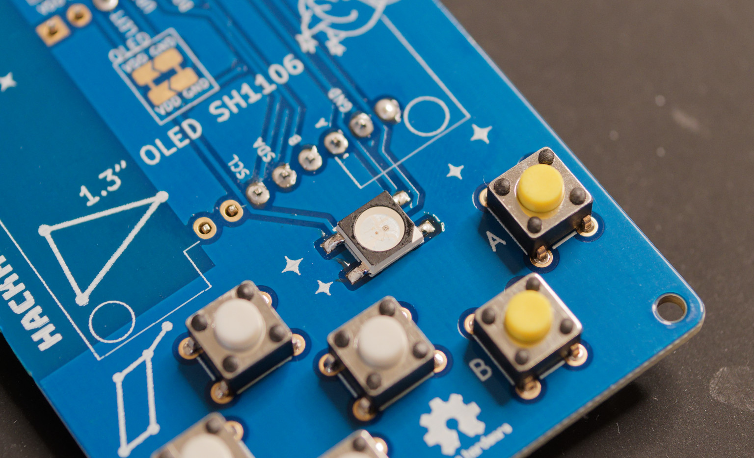
5. NeoPixel LED
-
Take the NeoPixel LED and the PCB.
-
Pretin one pad of the NeoPixel LED on the PCB.
-
Place the NeoPixel LED on the PCB and solder the pre tinned pin. Make sure the LED is aligned with the silkscreen on the PCB. The triangle should be on the bottom right.
-
Solder the remaining pins of the NeoPixel LED.
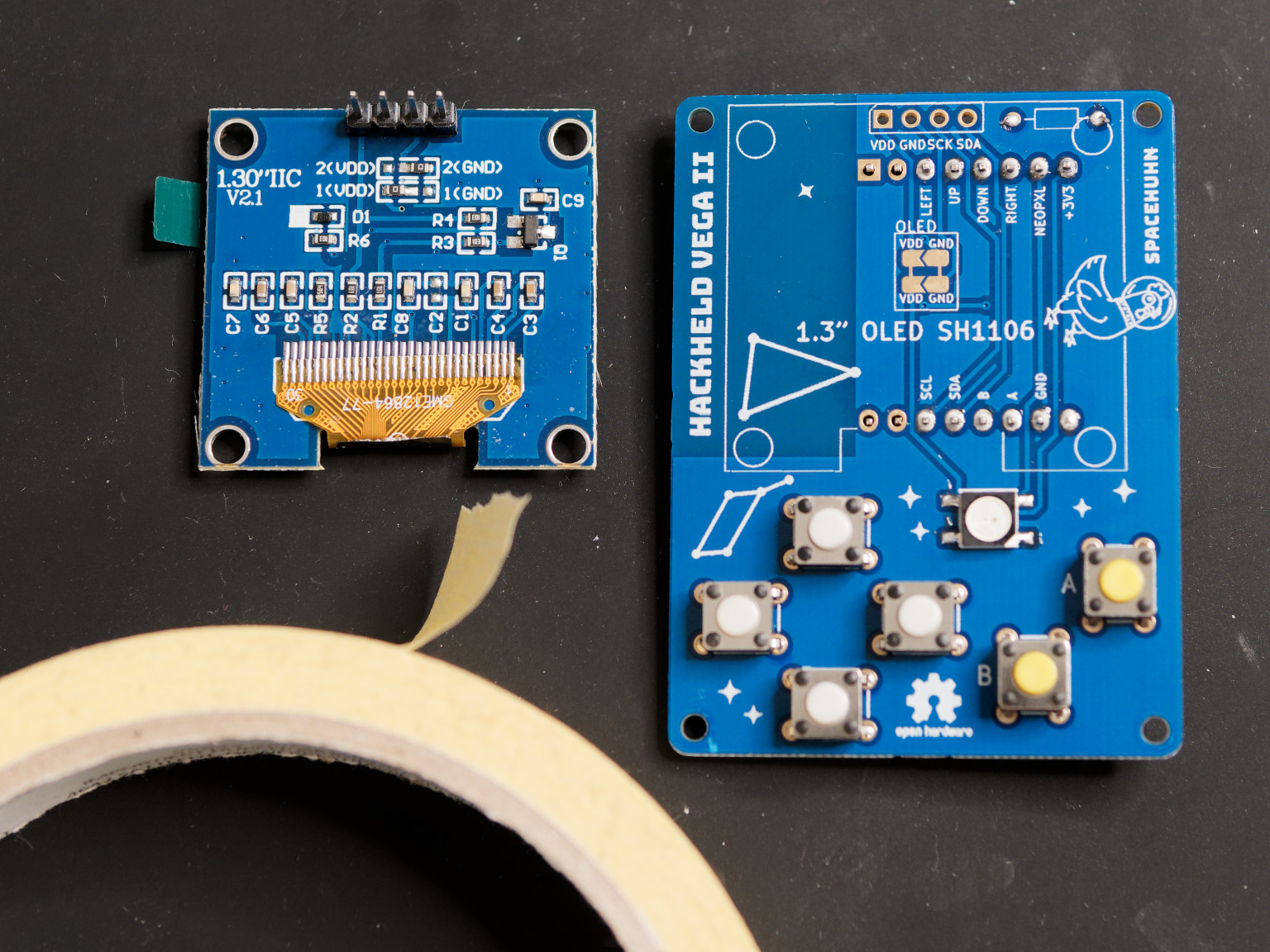
6. OLED display
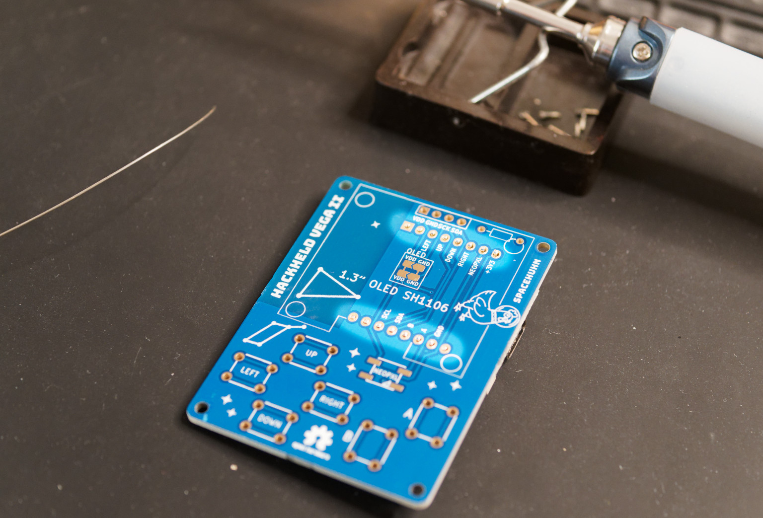
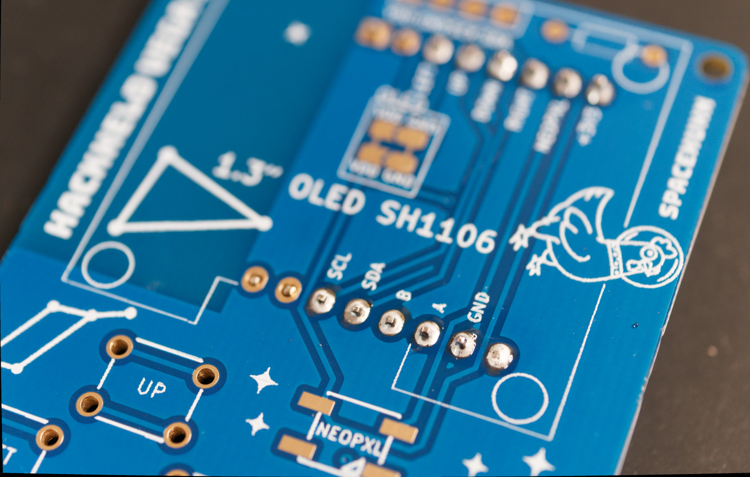
Make sure the OLED pinout matches the one on the front side of the PCB. It must be compatible with VDD GND SCK SDA. It's important that VDD and GND are at the same place because some displays have them swapped, which would create a short circuit.
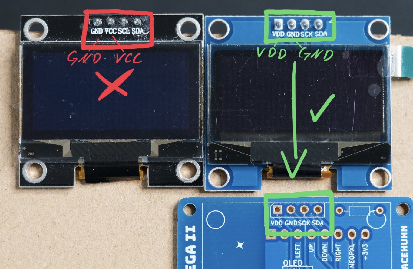 If you have the wrong display, scroll down for a workaround.
-
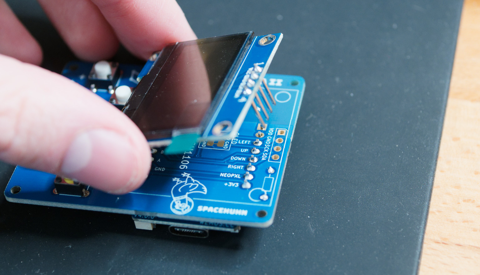
Take the OLED display, the PCB, and some tape.
-
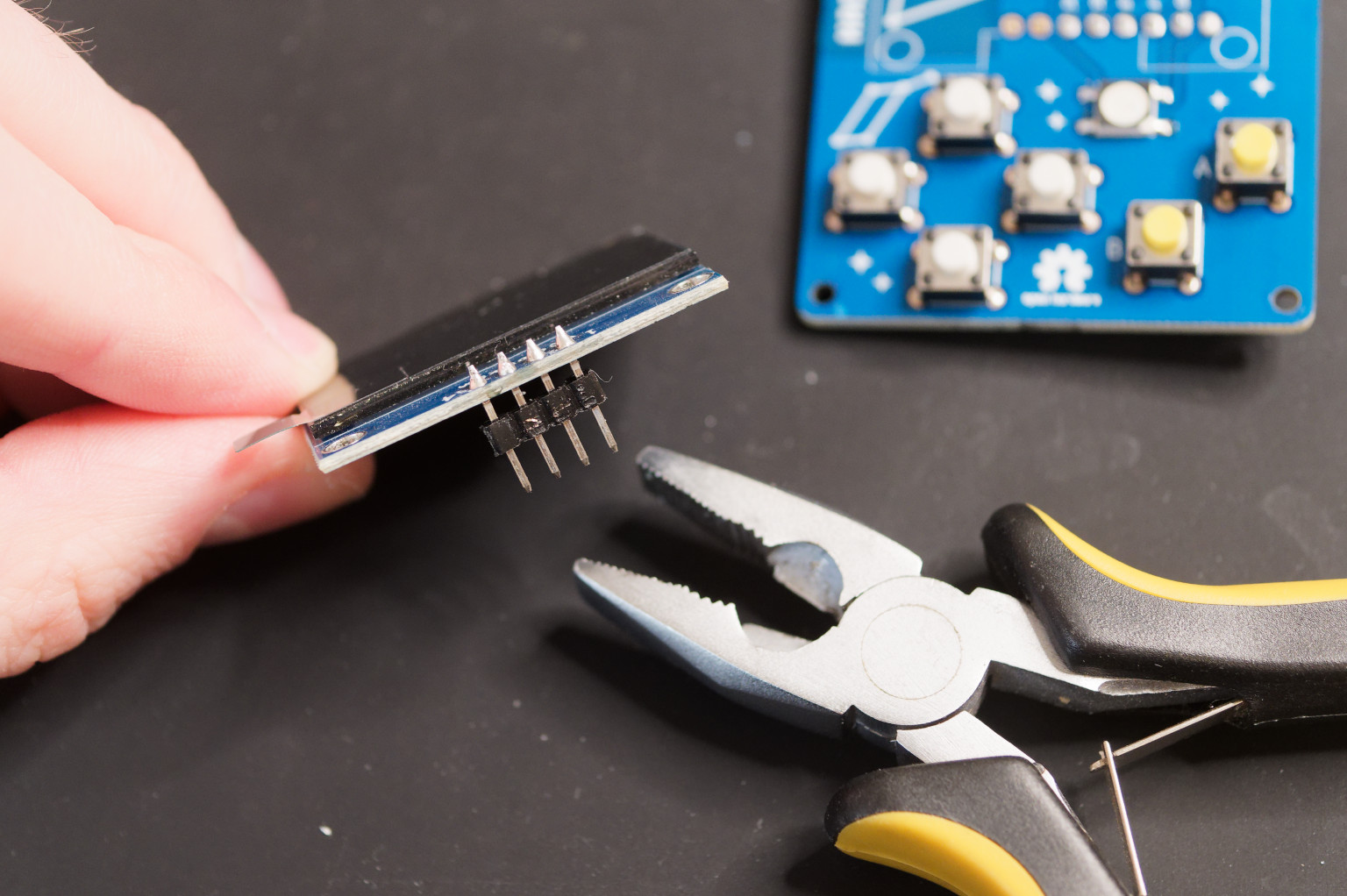
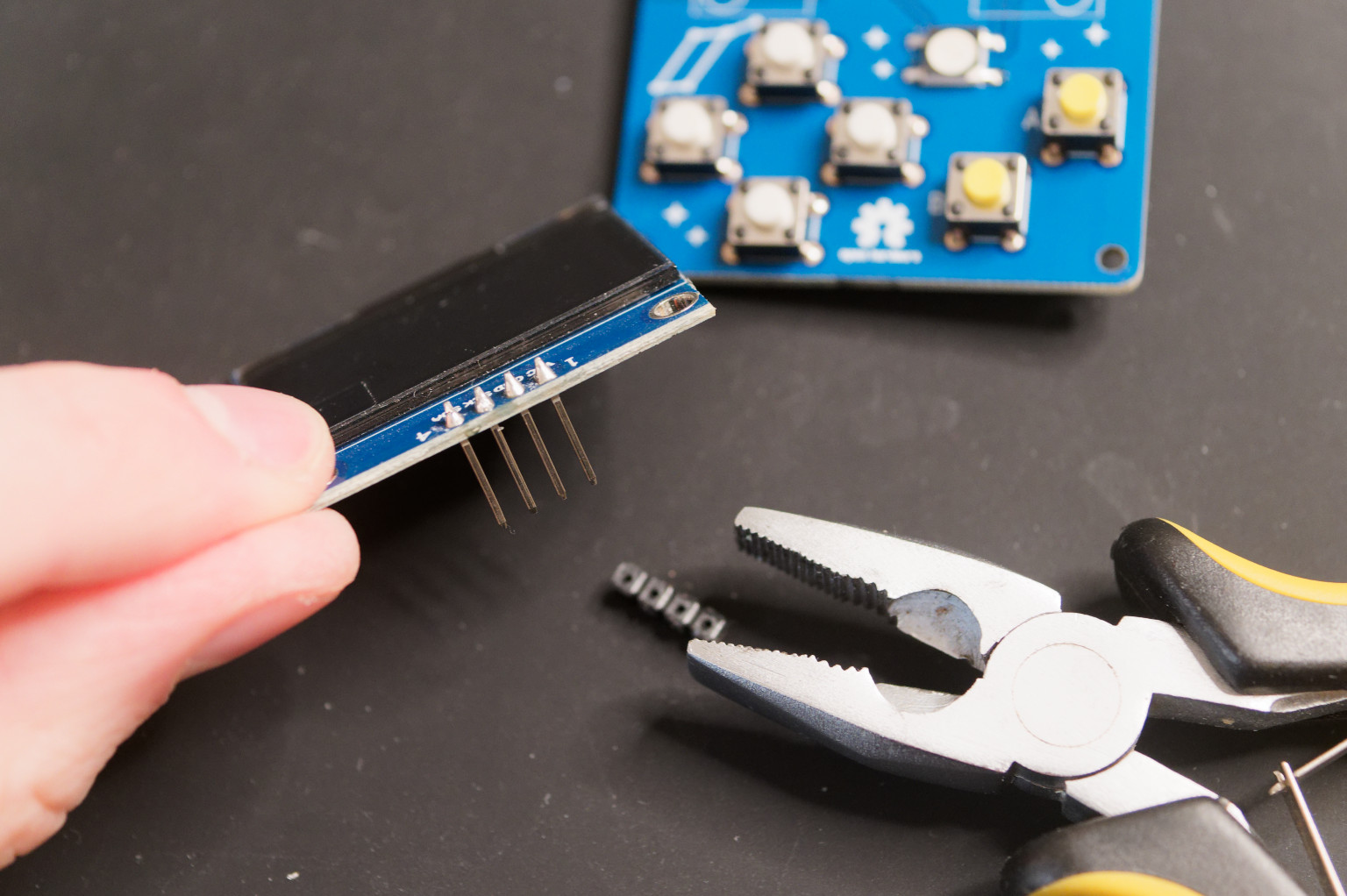
Remove the plastic part of the header pins from the OLED display with pliers. It's unnecessary and would prevent the display from sitting straight on the PCB. Avoid bending the pins while removing the plastic part, or bend them back afterwards.
-
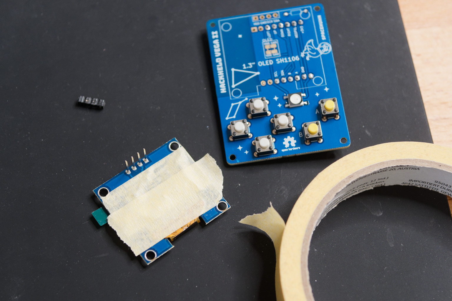
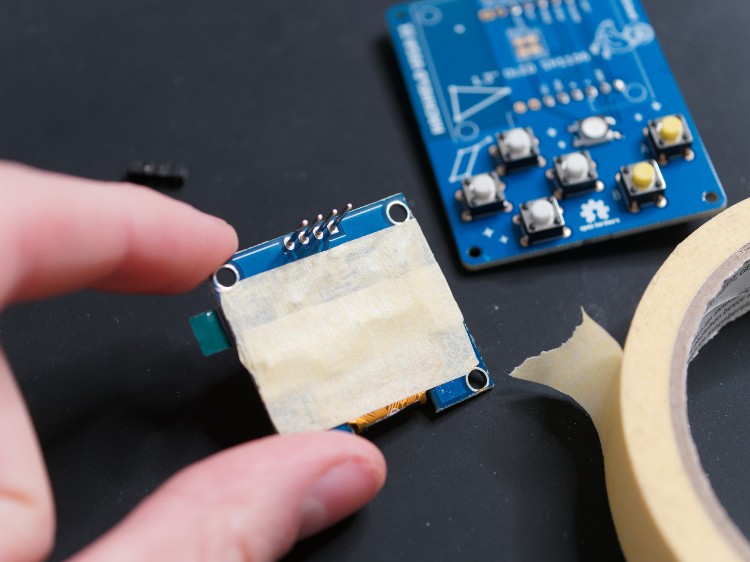
Add tape on the backside of the OLED display. This will prevent the display from shorting with the D1 Mini.
The kit now includes a piece of adhesive foam. You can use it instead of tape. It's easier to apply and you can use it to fix the display in place before soldering.
-
Put the OLED display on the PCB. Make sure the display is sitting straight on the PCB.
-
Solder one of the pins of the OLED display to the PCB. This will fix the display in place.
-
Make sure the display is sitting straight on the PCB. You can still bend it a bit.
-
Solder the remaining pins of the OLED display to the PCB.
-
Cut the pins of the OLED display.
7. Case
Place the PCB into the case and screw in the 4 screws.
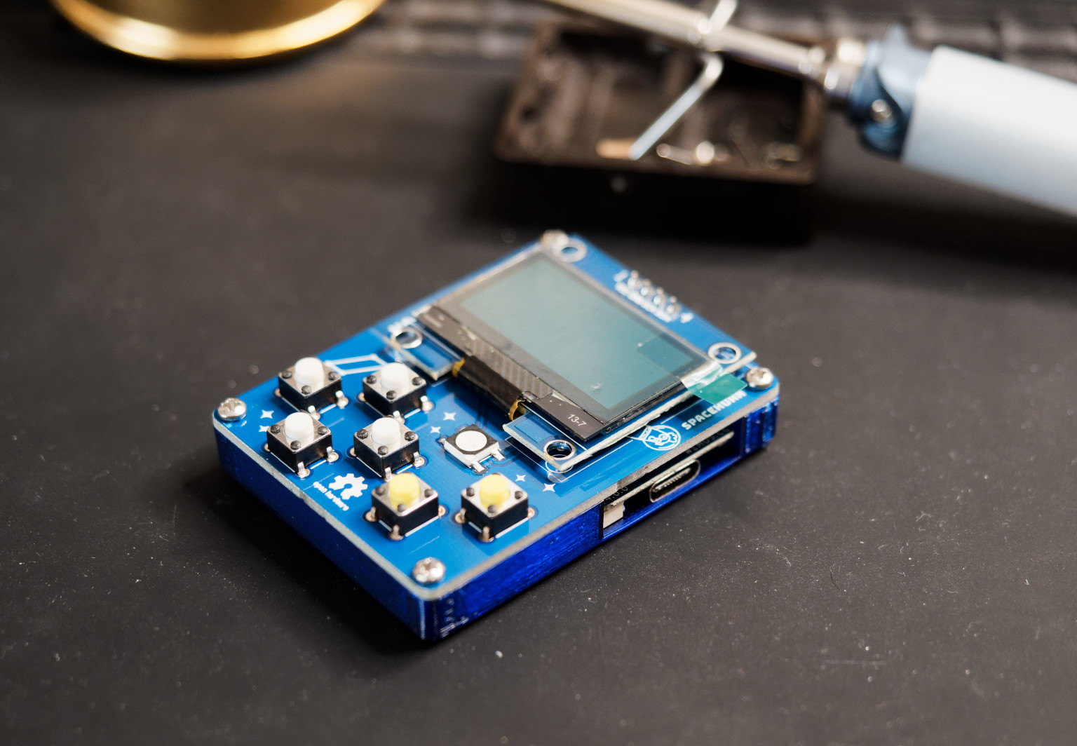
:partying_face: Congratulations! You have successfully assembled your HackHeld Vega! :partying_face:
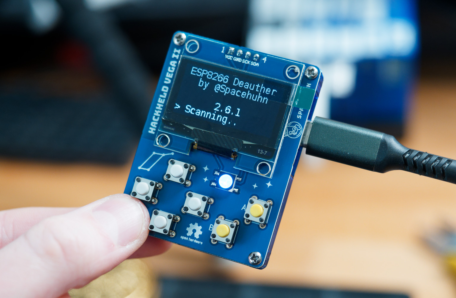
Check out firmware installation guide if you want to install the Deauther firmware.
Visit deauther.com to learn how to use the Deauther.
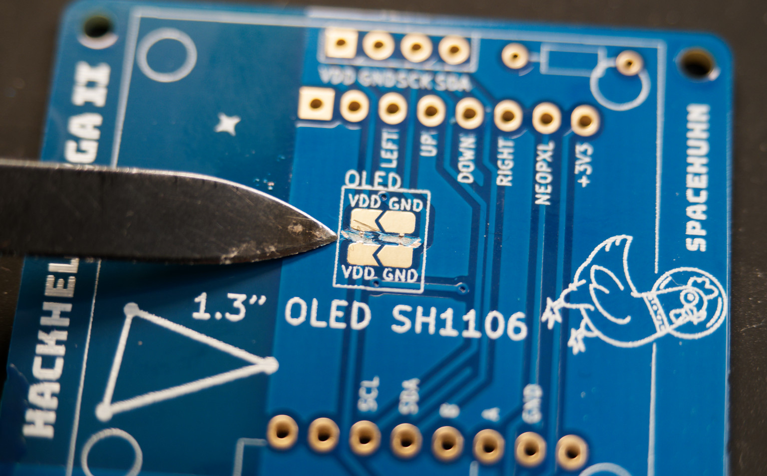
Workaround for swapped OLED
If VDD and GND are swapped on your OLED display, you can still use it.
-
Cut the vertical jumper bridges on the PCB with a knife.
-
Then solder the horizontal jumper bridges on the front side of the PCB.
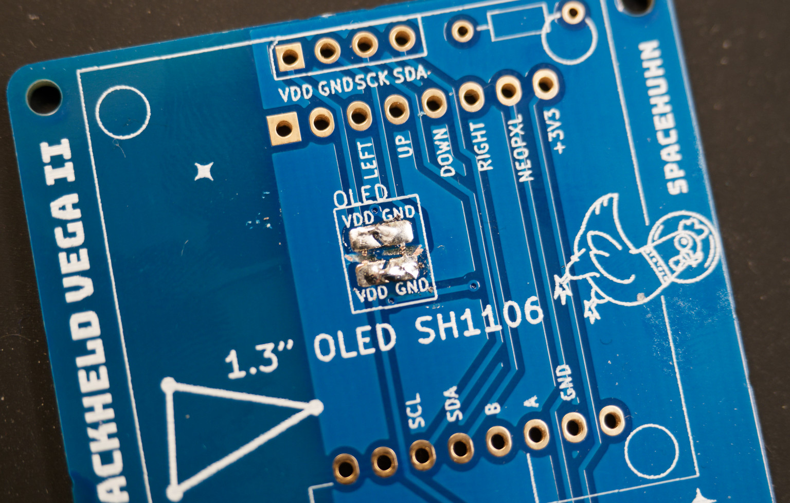 It doesn't have to look pretty to work. You can measure the voltage between
 VDDandGNDto ensure it's correct.
Now you can solder the OLED display to the PCB as described above.